华为UPS2000-G-3KRTL,华为3KvaUPS电源技术参数华为UPS2000-G-3KRTL,华为3KvaUPS电源技术参数华为UPS2000-G-3KRTL,华为3KvaUPS电源技术参数华为UPS2000-G-3KRTL,华为3KvaUPS电源技术参数
华为UPS,华为UPS2000-G-3KRTL,华为3KvaUPS

华为UPS2000-G-3KRTL详细参数
| 基本参数 |
| UPS类型 | 在线式 |
|---|
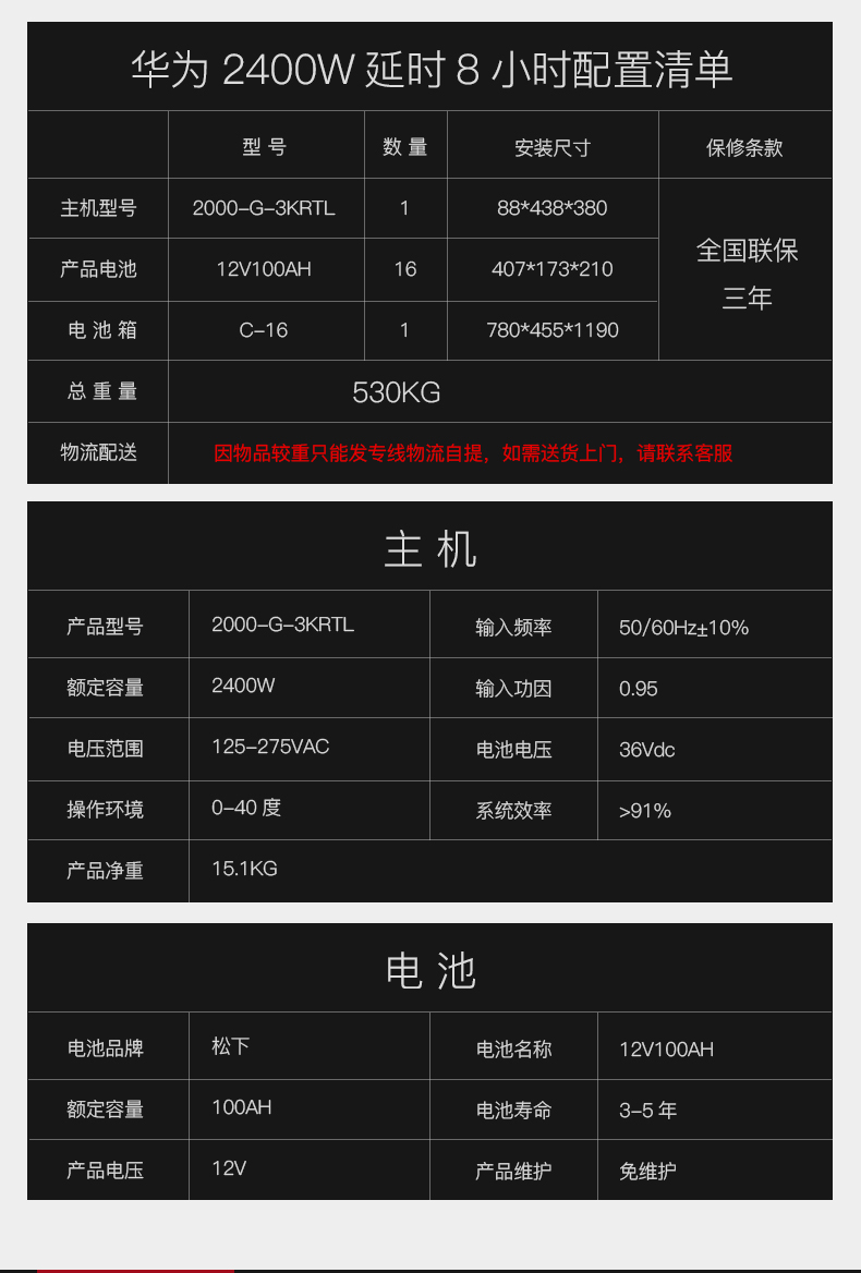
| 额定容量 | 3KVA |
|---|
| 负载功能 | 电脑、服务器、路由器等通讯设备 |
|---|
| 输入输出参数 |
| 输入电压范围 | AC 110-300V |
|---|
| 输入频率范围 | 40-70Hz |
|---|
| 输出电压范围 | AC 200/208/220/230/240V |
|---|
| 输出频率范围 | 市电模式50/60±3Hz,电池模式50Hz±0.05%Hz |
|---|
| 输出功因 | 0.7 |
|---|
| 其它输入参数 | RS232干接点 |
|---|
| 其它输出参数 | 效率:91% |
|---|
| 电池和运行时间 |
| 电池类型 | 阀控式铅酸电池 |
|---|
| 电压电流 | 96Vdc |
|---|
| 电池容量 | 18-999Ah(可设置) |
|---|
| 其它参数 |
| 外观尺寸 | 86×440×500mm |
|---|
| 其它性能 | 过载能力:
环境温度0-35℃:
105-110%:UPS在10分钟后会转旁路(市电模式)或者自动关闭(电池模式)
110-130%:UPS在1分钟后转旁路(市电模式)或者自动关闭(电池模式)
130-150%:UPS在3秒后转旁路(市电模式)或者自动关闭(电池模式)
>150%:UPS在最多0.5秒后转旁路(市电模式)或者自动关闭(电池模式)
环境温度35-40℃:
105-110%:在5分钟后会转旁路(市电模式)或者自动关闭(电池模式)
110-130%:UPS在30秒后转旁路(市电模式)或者自动关闭(电池模式)
130-150%:UPS在1.5秒后转旁路(市电模式)或者自动关闭(电池模式)
>150%:UPS在最多0.5秒后转旁路(市电模式)或者自动关闭(电池模式) |
|---|
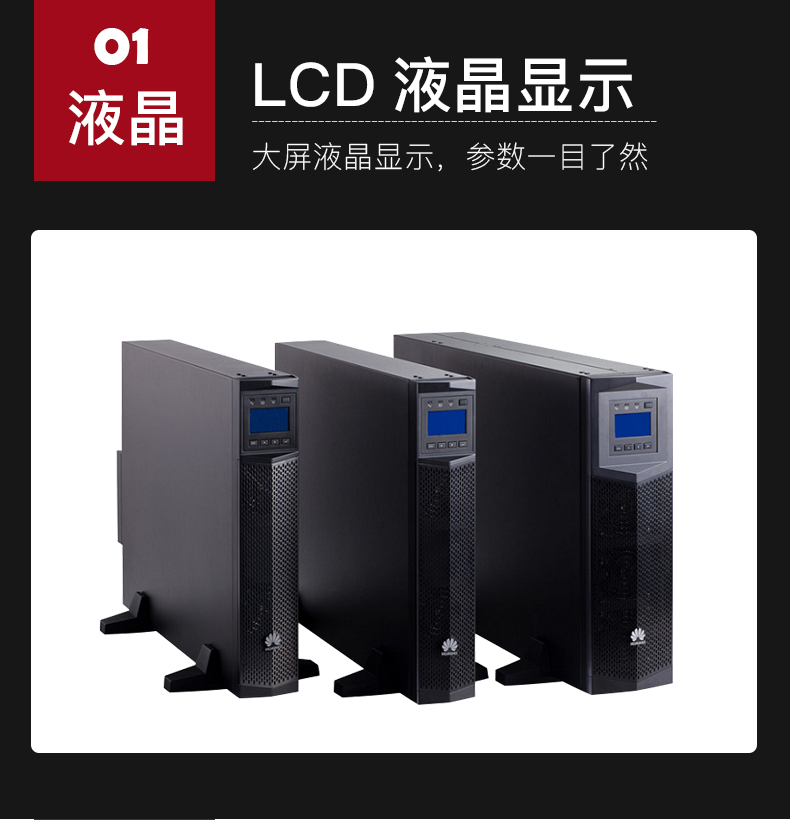
| 其它特点 | 塔式、机架式一体,标机,单进单出 |
|---|
6
序号 检查项目 验收标准
1 电缆布放 电缆布置合理,符合施工要求。
2 电缆连接
所有电缆连接处都不能有松动,用相应的力矩扳手校
验螺钉是否拧紧,连接正确,无破损。
3 USB、网口等电缆连接 USB、网口等控制电缆的连接必须正确,紧固。
4 电缆标签 电缆两头都需要标记,标签上标注要简洁易懂。
5 地线连接
需连接到机房内接地排,并连接牢靠,用万用表测量
UPS地线与机房地线排之间的电阻,阻值必须小于
0.1Ω。
6 扎带间距
扎带要均匀使用,且剪断处不留尖角,以免划伤维护
人员。
7 运行环境 清理机柜内外导电性粉尘及其他杂物。
安装后检查
5
操作与运行
6
开机/静音按钮 选择按钮 关机/输入按钮
按照下图所示,安装UPS的通信选配卡,选配卡的具体安装步骤,请参考《RMS-SNMP01B SNMP
卡 用户手册》,《RMS-RELAY01B 用户手册》,《RMS-MODBUS01B 用户手册》。1kVA~3kVA
UPS选配卡的安装方法相同,本文以3kVA图示安装位置。
4
安装选配卡
选配卡
选配卡
UPS2000-G-3KRTS UPS2000-G-3KRTL
7
7
UPS上电后,首次启动,请根据实际情况对输出电压、频率、电池等参数进行设置,参数设置具
体操作方法为:
1. 上电后UPS进入待机模式,按下面板上的“SELECT”5秒,进入UPS设置模式。
2. 在UPS设置模式中,按“SELECT”3秒以上用来选择下一个选项,按“ON/MUTE”3秒以上
用来选择上一个选项,按“OFF/ENTER”3秒以上用来确认选择;LCD显示文字含义详见第
8页7.1 LCD文字显示对照表。输出电压默认值为220V AC,可设置值包括:200V AC、208V
AC、220V AC、230V AC、240V AC。频率默认值为AUT,可设置值包括50Hz、60Hz、
AUT。电池容量标机不可设,长机默认18Ah,设定范围为18Ah~999Ah。
如果需要了解更多参数设置,请详细阅读《UPS2000-G-(1kVA-3kVA) 用户手册》。
1. 电池节数不可设,1kVA标机内置电池固定为2节,2kVA标机内置电池固定为4节, 3kVA标机内置
电池固定为6节。
2. 1kVA长机外接电池固定为3节,2kVA长机外接电池固定为6节, 3kVA长机外接电池固定为8节。
3. 长机输出充电电流固定为4A,不可设。外接电池包或电池组时,所选电池总容量必须在18Ah以上,
以免造成电池损坏。如果外接电池包或电池组容量大于40Ah,建议再购买外置充电器,增大充电
电流,否则回充时间太长。
4. 标机电池容量不可设,默认为9Ah,充电电流固定为1A,不可设。长机电池容量为各组电池容量
的总和,需要根据实际情况进行设置,出厂默认18Ah,例如接入电池规格9Ah/12V,8节串联为
一组,两组电池并联接入UPS,“电池容量”为9Ah+9Ah=18Ah。此参数会影响UPS计算备电时
间,如果设置错误会导致LCD面板上的备电时间显示错误。
5. 在市电接入的情况下,长机首次接入电池包/电池,必须手工进行一次电池自检,以便确认电池连
接是否正常。手工电池自检方法为:按下前面板上的“ON/MUTE”5秒,则UPS转到电池模式进
行电池浅放电测试,10秒之后自动转回市电模式。
6. 第一次使用时,电池要经过5个小时充电。如果充电未满5个小时,电池放电时间将会减少。
设置UPS 关键参数 6.1
1. 如果在UPS设置模式下,10秒以上没有进行任何操作,则LCD回到主页面。
2. 如果长机未外接电池包,则蜂鸣器会一直响进行提示。
3. UPS会自动进行电池自检,一周一次,如果电池有问题,则会告警。
UPS上电之后,默认无输出。按下前面板上的“ON/MUTE”5秒以上,开启UPS逆变输出,系统切
换到逆变输出状态,UPS出厂默认逆变输出220V。
UPS 开启逆变 6.2
• 市电模式:按下“OFF/ENTER”按键2秒以上,UPS 会关闭逆变进入待机模式,如已设置并启用
旁路功能,则进入旁路模式。
• 电池模式:按下“OFF/ENTER”按键2秒以上,便可关闭在电池模式下的UPS。
UPS 关机 6.3
8
缩写 实际显示内容 意义 缩写 实际显示内容 意义
ENA 启用 FRE 频率
DIS 停用 BVU 旁路电压过高
ESC 退出 BVL 旁路电压过低
CF 频率转换 CAP 容量
TP 温度 DT 放电时间
CH 充电 ECO 节能模式
FU 旁路频率不稳定 VU 高电压
EE EEPROM错误 VL 低电压
VOT 电压
AUT 恒频模式
BUZ 蜂鸣器静音 AST 自动开机
故障类别 蜂鸣告警音
电池模式 每4秒响1声
次要告警 每秒响1声
过载 每秒响2声
紧急告警 连续鸣响
旁路模式 每10秒响1声
FAQ
7
LCD 显示 文字 对照表 7.1
蜂鸣器告警音 7.2
9
问题情形 可能原因 解决方法
主电源正常,可是LCD不
亮,且无蜂鸣器响起。
市电输入电源可能松脱,未接好。 检查输入电源线有无松脱的情形。
市电输入误接在UPS的输出端。 将市电输入电源线正确的插入UPS
的市电输入端。
LCD面板上有图示 和
在闪烁,同时,每秒
会有蜂鸣器响一声。
外接或内接电池的连接方式有误。 请确认所有电池均以正确方式接好。
LCD面板上有图示 和
闪烁,同时每秒会蜂鸣器
响两声。
UPS过载。 请由UPS输出端移除负载超出的部
分。
UPS过载,而UPS目前正以旁路方
式直接以电力网对设备供电中。
请由UPS 输出端移除负载超出的部
分。
短时间内多次过载,UPS已经锁定在
旁路模式,直接将设备连上主电源中。
请先由UPS输出端移除负载超出的
部分,然后,关闭并重新启动UPS
系统。
电池提供的备电时间比规
格时间还短。
电池可能未充满。 请先充电至少5小时后,再检查电池
电量。如果电池电量仍低,请联系
经销商。
电池故障。 请联系经销商,要求更换电池。
8
典型故障处理
10
告警
ID
告警
原因
ID
告警 名
称
告警
级别
告警清
除方式
触发条件 对系统的影响 修复建议
10 1 旁路电
压异常
次要 自动
清除
旁路电压超出
范围。
保持原来工作状态,
若机器在旁路模式,
则会转入待机模式,
无输出。
可能故障原因:
旁路输入电压超
过范围。
修复措施:检查
旁路输入电压是
否超过设置范围,
如超过可修改旁
路电压范围或等
待旁路输入电压
恢复正常。
2 旁路频
率异常
次要 自动
清除
旁路频率超出
旁路频率范围。
不影响系统的正常
供电,保持原来工
作状态,若机器在
旁路模式,则会转
入待机模式,无输
出。
可能故障原因:
旁路频率不在规
定的范围内。
修复措施:检查
旁路输入频率,
如异常则等待主
路恢复正常。
22 1 电池未
接
次要 自动
清除
电池未接、连
接异常或者电
池损坏。
不影响系统的正常
供电。
• 可能故障原因:
电池未接。
修复措施:接
入电池。
• 可能故障原因:
电池接触不良。
修复措施:检
查电池接线,
如有松动请紧
固。
25 1 电池过
压
紧急 手动
清除
每个电池电压
超过15V(在
开机的情况
下)。
电池节数超过实际
所需的数量:
• 开机前电池包接
入,此时UPS无
法开机。
• 正常运行中,接
入电池包,机器
会转旁路。
• 可能故障原因:
实际电池节数
不满足规格要
求。
修复措施:检
查实际接入电
池节数是否满
足规格要求。
• 可能故障原因:
充电器异常。
修复措施:检
查充电器,断
开电池瞬间测
量充电器电压
是否正常。
更多参数及告警信息详见《UPS2000-G-(1kVA-3kVA) 用户手册》。
9
典型告警处理
11
告警
ID
告警
原因
ID
告警 名
称
告警
级别
告警清
除方式
触发条件 对系统的影响 修复建议
25 1 电池过
压
次要 自动
清除
(转
到电
池模
式后
自动
消失)
每节电池电压
超过14.7V。
UPS会转到电池模
式放电,直至产生
电池电压低压告警,
然后自动转到市电
逆变,自动开启充
电器充电。
• 可能故障原因:
实际电池节数
不满足规格要
求。
修复措施:检
查实际接入电
池节数是否满
足规格要求。
• 可能故障原因:
充电器异常。
修复措施:检
查充电器,断
开电池瞬间测
量充电器电压
是否正常。
26 1 电池低
压
紧急 手动
清除
每个电池电压
低于5V(在开
机的情况下)。
电池节数少于实际
所需的数量:
• 开机前电池包接
入,此时UPS无
法开机。
• 正常运行中,接
入电池包,机器
会转旁路。
• 可能故障原因:
实际电池节数
不满足规格要
求。
修复措施:检
查实际接入电
池节数是否满
足规格要求。
• 可能故障原因:
无正常市电,
电池放电导致
的电池电压低。
修复措施:在
非电池测试时,
尽可能接入市
电。
次要 自动
清除
每节电池电压
低于11.28V。
产生机器电压低告
警。
29 1 电池需
要维护
次要 自动
清除
电池自检模式
时,电池电压
低于电池更换
电压(11V)。
保持原来工作状态。 • 可能故障原因:
实际电池节数
不满足规格要
求。
修复措施:检
查实际接入电
池节数是否满
足规格要求。
• 可能故障原因:
电池可能损坏。
修复措施:联
系经销商或华
为客户服务中
心更换电池。
次要 自动
清除
每个电池电压
低于5V或每个
电池电压超过
15V(在未开
机时告警)。
不影响系统的正常
供电,但UPS不允
许开机。
12
告警
ID
告警
原因
ID
告警 名
称
告警
级别
告警清
除方式
触发条件 对系统的影响 修复建议
42 17 内部故
障
紧急 手动
清除
母线电压超过
450V。
运行过程中如产生
此告警,UPS转旁
路。
• 可能故障原因:
主路瞬时高压
冲击。
修复措施:清
除故障后重新
开机。
• 可能故障原因:
输出带感性负
载、整流性负
载等特殊类型
负载。
修复措施:检
查负载类型是
否属于产品支
持类型。
• 可能故障原因:
硬件损坏。
Six
Item number acceptance criteria
1 the layout of cable laying cables is reasonable and accords with construction requirements.
2 cable connection
All cable connections must not be loosened. Use the corresponding torque wrench.
Whether the screw is tightened, the connection is correct and no damage is found.
3 the connection of control cables such as USB, mesh and other cables connecting USB, mesh port must be correct and fastened.
4 the cable label cable must be marked at both ends, and the label should be concise and easy to understand.
5 ground connection
Connect to the grounding line in the engine room, and connect it firmly with multimeter.
The resistance between the UPS ground wire and the ground wire row of the engine room must be less than the resistance value.
0.1 Omega.
6 tape spacing
The tape should be evenly used, and no sharp corners should be left to avoid scratching.
People.
7 running environment to clean conductive dust and other sundries inside and outside the cabinet.
After installation inspection
Five
Operation and operation
Six
Boot / mute button selection button, shutdown / input button
Refer to RMS-SNMP01B SNMP for details of how to install UPS communication adapters and adapters as shown in the following figure
Card user manual, "RMS-RELAY01B user manual", "RMS-MODBUS01B user manual". 1kVA ~ 3kVA
The installation method of the UPS matching card is the same. In this paper, the installation position is shown in 3kVA diagram.
Four
Install matching cards
Selection card
Selection card
UPS2000-G-3KRTS UPS2000-G-3KRTL
Seven
Seven
After the UPS power on, the first time to start, please according to the actual situation of the output voltage, frequency, battery and other parameters set, parameter settings
The body operation method is:
1. after power on, UPS enters the standby mode, and enters the UPS setting mode according to the "SELECT" 5 seconds on the following board.
2. In UPS setup mode, press SELECT for more than 3 seconds to select the next option, and press ON/MUTE for more than 3 seconds
To select the last option, press "OFF / ENTER" for more than 3 seconds to confirm the selection; LCD display text meaning see
8 pages 7.1 LCD text display comparison table. The default value of the output voltage is 220V AC, which can be set to: 200V AC, 208V
AC, 220V AC, 230V AC, 240V AC. The default value of frequency is AUT, which can set values including 50Hz, 60Hz,
AUT. The battery capacity standard machine can not be set, the long machine acquiescence 18Ah, the set range is 18Ah ~ 999Ah.
If you need to know more parameter settings, please read the UPS2000-G- (1kVA-3kVA) user manual in detail.
1. The number of batteries is not set. The built-in batteries of 1kVA standard machine are fixed to 2, the built-in batteries of 2kVA standard machine are fixed to 4, and the built-in batteries of 3kVA standard machine are fixed to 3.
The battery is fixed to 6 knots.
The external batteries of the 2.1 kVA long engine are fixed to 3 sections, the external batteries of the 2 kVA long engine are fixed to 6 sections, and the external batteries of the 3 kVA long engine are fixed to 8 sections.
3. the charging current of the long machine output is fixed to 4A and can not be set. When the battery pack or battery pack is connected, the total capacity of the selected battery must be above 18Ah.
So as not to cause battery damage. If the external battery pack or battery pack capacity is greater than 40Ah, it is recommended to buy external charger and increase charging.
Current, otherwise the charging time will be too long.
4. the battery capacity of the standard machine can not be set, the default is 9Ah, the charging current is fixed to 1A, and it can not be set. The battery capacity of long machine is battery capacity of each group.
The total, need to be set according to the actual situation, factory default 18Ah, such as access battery specifications 9Ah / 12V, 8 in series as
One group, two batteries connected to UPS in parallel, and the battery capacity is 9Ah+9Ah=18Ah. This parameter will affect the computation power of UPS.
If the error is set, the standby time on the LCD panel will be displayed wrong.
5. In the case of power supply, the battery pack/battery must be checked manually for the first time when the mainframe is connected to the battery pack/battery, so as to confirm the battery connection.
Is the connection normal? The manual battery self test method is: press the "ON/MUTE" 5 seconds on the front panel, then UPS goes to the battery mode.
Battery discharge test will be carried back to power mode 10 seconds later.
6. when used for the first time, the battery will be charged for 5 hours. If the charge is less than 5 hours, the battery discharge time will be reduced.
Set UPS key parameters 6.1
1. if LCD does not do any more than 10 seconds in the UPS settings mode, then go back to the main page.
2. if the machine does not connect the battery pack, the buzzer will keep ringing.
3. UPS will automatically carry out battery self inspection once a week, if the battery is defective, it will alarm.
After UPS is powered on, no output is allowed by default. Press the "ON/MUTE" for more than 5 seconds on the front panel, turn on the UPS inverter output, and cut the system.
Changing to the inverter output state, UPS factory default inverter output 220V.
UPS turn on inverter 6.2
* Power mode: Press the "OFF/ENTER" button for more than 2 seconds, and UPS will turn off the inverter and enter standby mode, if set and enabled.
The bypass function goes into the bypass mode.
Battery mode: by pressing the "OFF/ENTER" button for more than 2 seconds, the UPS in battery mode can be switched off.
UPS turn off 6.3
Eight
Abbreviations actually display content meaning abbreviation and actually display content meaning.
ENA enable FRE frequency
DIS shutdown BVU bypass voltage is too high.
ESC exit BVL, bypass voltage is too low.
CF frequency conversion CAP capacity
TP temperature DT discharge time
CH charging ECO energy saving mode
FU bypass frequency instability VU high voltage
EE EEPROM error VL low voltage
VOT voltage
AUT constant frequency mode
BUZ buzzer mute AST boot automatically
Fault category buzz warning tone
Battery mode sounded 1 times every 4 seconds.
Secondary alarm sounds 1 times per second.
Overload sounds 2 times per second.
Emergency alarm continues to ring.
Bypass mode sounds 1 times every 10 seconds.
FAQ
Seven
LCD display text comparison table 7.1
Buzzer warning tone 7.2
Nine
Problem situations, possible causes, solutions
The main power supply is normal, but LCD is not.
Bright and no buzzer sounded.
The power input may be loose and not ready. Check whether the input power cord is loose.
City electricity transmission
华为-48v通信高频直流开关电源
华为通信电源,华为开关电源,华为-48v开关电源,华为高频开关电源,华为直流电源
华为通信电源,华为电源官网,华为高频开关电源,华为-48v开关电源,华为开关电源模块,华为网络机柜,华为服务器机柜,华为室外一体化机柜,华为OLT电源,华为直流电源,华为开关电源,华为综合柜,华为UPS,UPS5000-E,UPS2000-A,UPS2000-G,UPS8000-D,UPS5000-A,华为TP48200,华为TP48300,华为TP48600