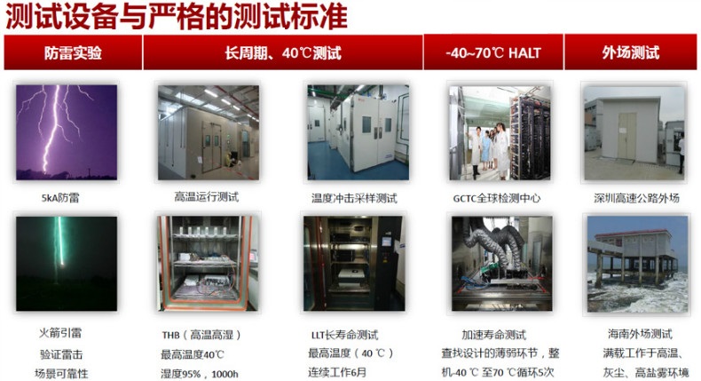
华为UPS5000-A-40KTTL,华为40kvaUPS电源技术参数华为UPS5000-A-40KTTL,华为40kvaUPS电源技术参数华为UPS5000-A-40KTTL,华为40kvaUPS电源技术参数
华为UPS,华为UPS5000-A-40KTTL,华为40KvaUPS

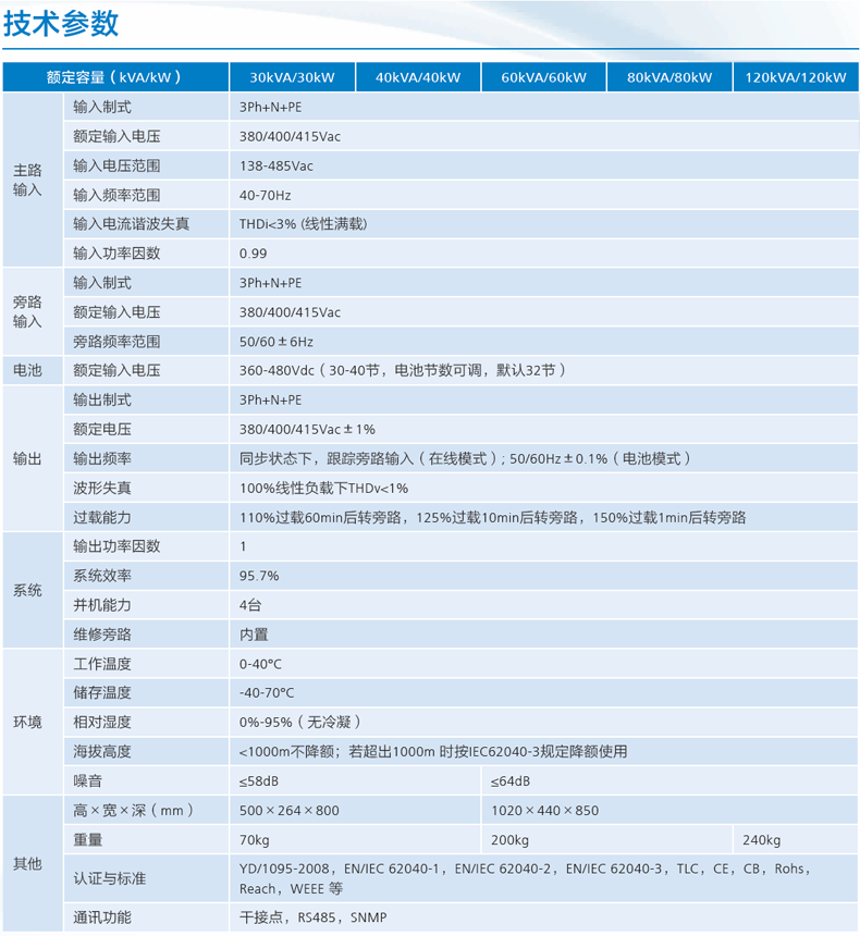
| 基本参数 |
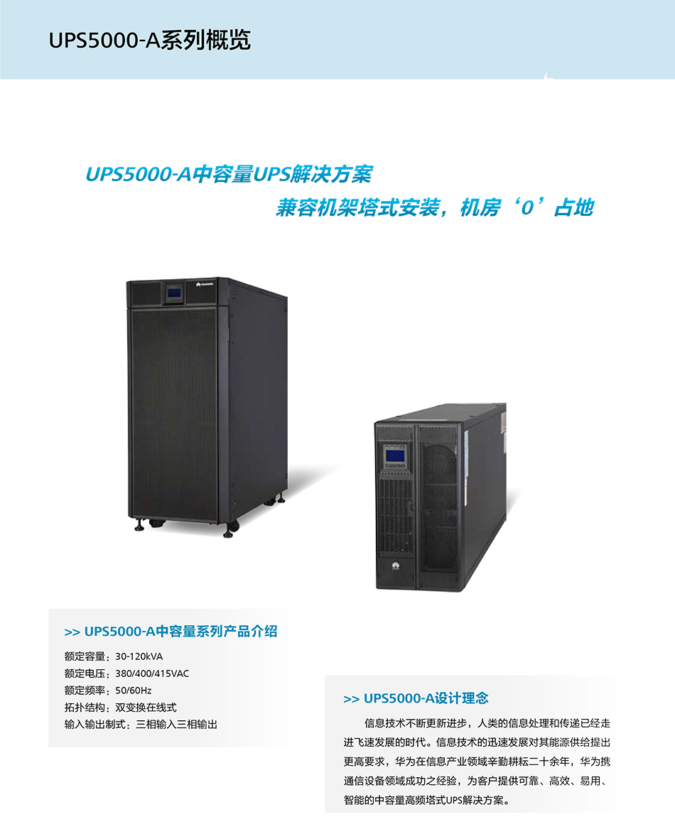
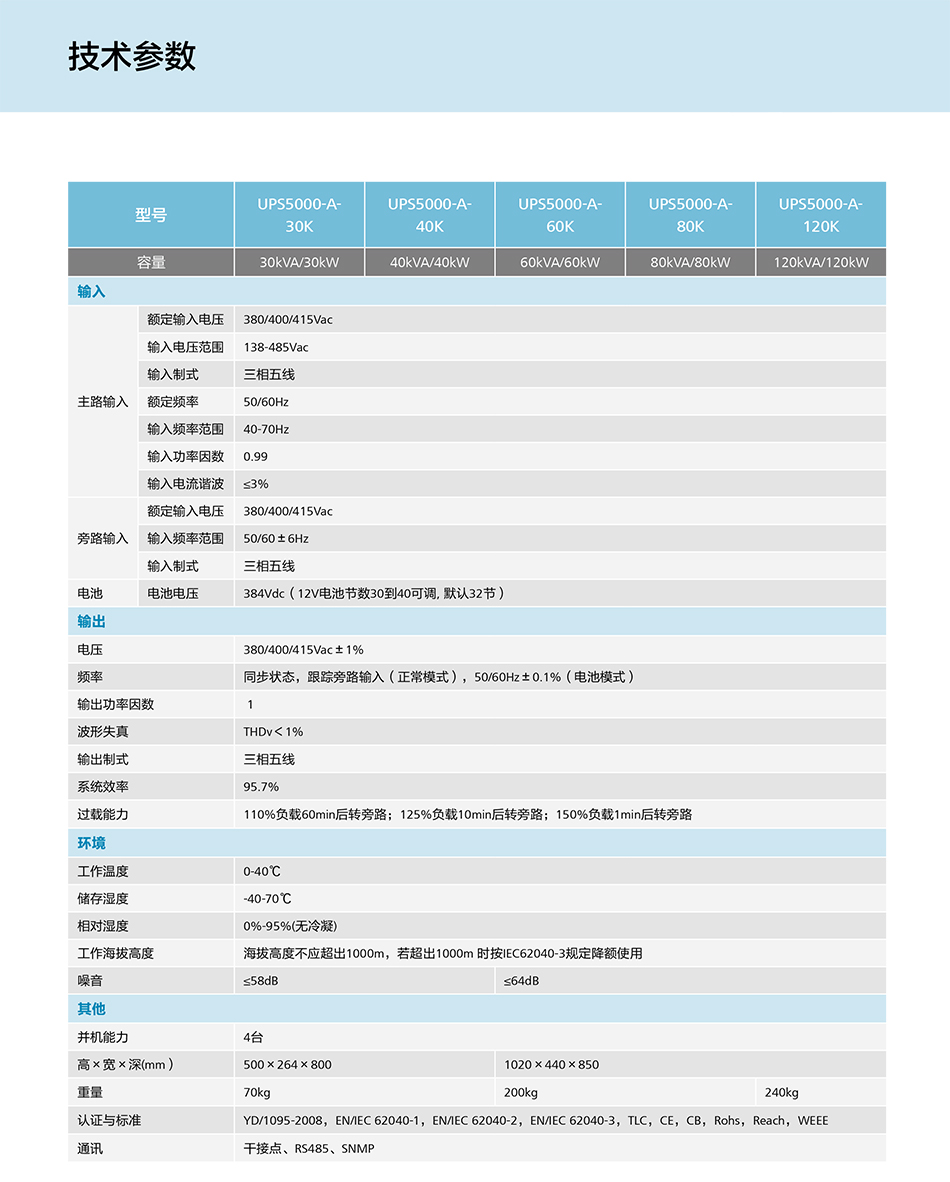
| 额定电压 | AC 380/400/415V |
|---|
| 额定频率 | 50/60Hz |
|---|
| 输入输出参数 |
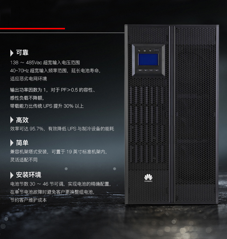
| 输入电压范围 | AC 138-485V |
|---|
| 输入频率范围 | 40-70Hz |
|---|
| 输入功因 | 0.99 |
|---|
| 输出电压范围 | AC 380/400/415(±1%)V |
|---|
| 输出功因 | 1 |
|---|
| 其它输出参数 | 效率:95.7% |
|---|
| 通信和管理 |
| 过载能力 | 110%负载60分钟后转旁路,125%负载10分钟后转旁路,150%负载1分钟后转旁路) |
|---|
| 其它参数 |
| 外观尺寸 | 500×264×800mm |
|---|
| 产品重量 | 70kg |
|---|


、


 UPS5000-A-(30kVA-120kVA) 快速指南
1
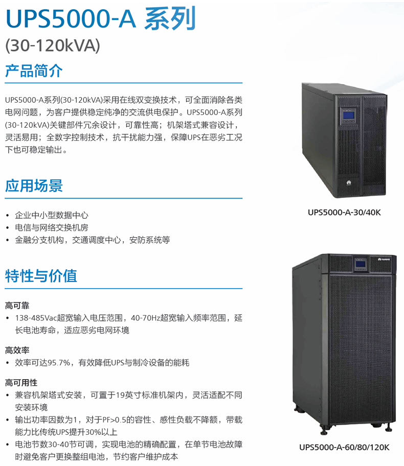
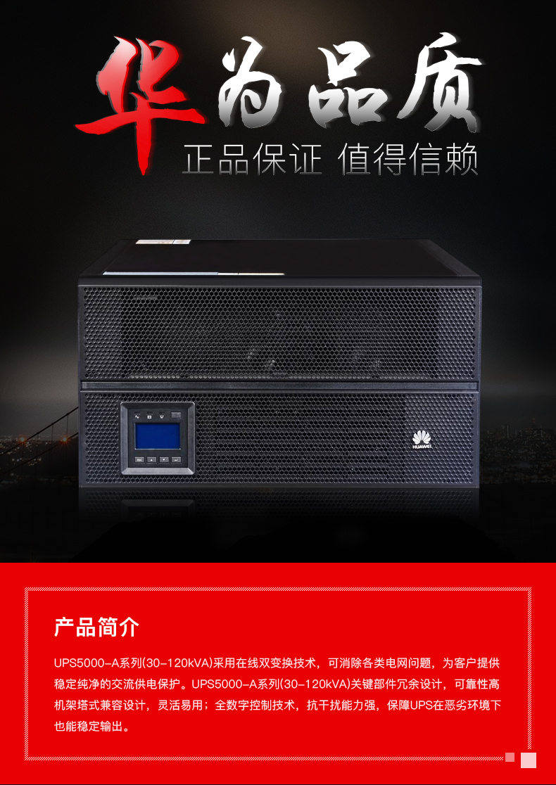
产品简介
型号 容量配置 重量
尺寸(高 × 宽 × 深)
UPS5000-A-30KTTL
UPS5000-A-40KTTL
30kVA、40kVA
70kg
500mm×264mm×800mm(塔式)
264mm×500mm×800mm(机架式)
型号 容量配置 重量
尺寸(高 × 宽 × 深)
UPS5000-A-60KTTL
UPS5000-A-80KTTL
60kVA、80kVA
160kg
1020mm×440mm×850mm
UPS5000-A-120KTTL
120kVA
200kg
右图为UPS拆除前面
板和监控显示单元后
所呈现的状态。
监控显示
单元
前面板
旁路单元 功率单元
监控显示
单元
前面板
旁路单元
功率单元
维修旁路开关
右图为UPS拆除前面
板和监控显示单元后
所呈现的状态。
2. 将就绪开关置于未就绪“ ”的状态,拆除
功率单元和旁路单元。
2
安装流程
1. 安装设备前请详细阅读用户手册了解产品信息及安全注意事项。
2. 安装操作设备时,必须使用绝缘工具。
3. UPS必须由华为或其代理商认证的工程师进行安装、调测和维护,否则可能危及人身安全并且导
致设备故障,由此引起的UPS损坏不属保修范围。
2
安装UPS
场景1 :塔式安装
1. 组装支撑底座。
场景2 :机架式安装
30kVA/40kVA UPS 2.1
3. 收起后端抬手和安装前面板。
1. 拆除机箱左右侧板、抬手、监控显示单元。
后端抬手
前端抬手
2. 拆除前面板,拉出后端抬手,将主机置于支撑
底座上进行固定。
现用挂耳
原挂耳
3
3. 机架上安装导轨(导轨总高度为2U),固定
导轨后端。
5. 将插框插入机架并固定。将功率单元、旁路
单元装入插框,并用螺钉进行固定。
6. 安装监控显示单元。
7. 安装前面板,同时将前面板上的华为Logo顺时针旋转90°。
4. 更换功率单元的挂耳。
4
安装流程
1. 根据划线模板确定安装孔位,打孔并安装膨胀管。 2. 调节地脚螺栓,先确保地脚螺栓触地,再调
平UPS。
3. 拆除UPS的前盖板。
单位:mm
机柜后
方边缘
L型弯角件固定孔位
前
后
墙体
4. 用L型弯角件将机柜固定在地面。
1. 机架式安装要求对应机架必须符合IEC297标
准,机架深度不小于1100mm,同时机架中导
轨安装深度应大于820mm。
2. UPS较重且需要下走线,建议将UPS安装在机
架的最下方。
场景1 :地面安装
场景2 :机架式安装
60kVA/80kVA/120kVA UPS 2.2
1. 先在机柜两侧安装导轨,然后在机架前后各安装一个加强梁。
2. 在机架前端左右两侧安装浮动螺母。
浮动螺母
3. 移除前盖板、功率单元。
4. 安装挂耳,将机箱装入机架。
5
5. 调节地脚螺栓,使机箱底端与刻度板上刻度线平齐,并调整UPS水平。
“Edge of cabinet”
(柜体边缘)刻度线
6. 将UPS挂耳与机架固定,然后将功率单元装回UPS机箱,并将功率单元就绪开关全部置于就绪“ ”
状态。
6
7
3
安装线缆
• 制作线缆时,务必远离机柜,避免线缆碎屑不小心进入机柜,引起上电打火造成人身伤害及设备
损害。
• 安装线缆完毕后,请及时清理机柜。务必保障机柜内和四周无异物。
走线路径仅供参考,请根据实际情况连接。
30kVA/40kVA UPS 3.1
1. (主旁同源无需进行此步骤)拆除主路和旁路输入之间的连接铜排。
8
2. 连接地线、功率线和信号线。
从正负电池组中间引出的线即为电池N线。
以40节电池为例,正、负电池组各20节电
池,从正、负电池中间引出的线即为电池
N线。
信号线
电池线
旁路输入线(主旁同源
时无需连接)
主路输入线
图中信号线的数量和颜色仅为示意。
输出线
丝印 接口说明 螺栓规格 扭力力矩
1L1,1L2,1L3,N 主路输入 M6×16 4N•m
2L1,2L2,2L3,N 旁路输入 M6×16 4N•m
+,N,- 电池输入 M8×16 8N•m
U,V,W,N 输出 M6×16 4N•m
PE 保护地 M6×16 4N•m
9
60kVA/80kVA/120kVA UPS 3.2
1. 拆除机箱背面的配电单元盖板。
2. 根据线缆数量和位置,拆除机柜底部的
小盖板。
3. (主旁同源无需进行此步骤)拆除主路和旁路
输入之间的连接铜排。
4. 连接地线、功率线和信号线。
• 主路输入和旁路输入共
用N排。
• 图中线缆数量仅供参考。
• 主旁同源时,不需要连
接旁路输入线缆。
信号线
10
从正负电池组中间引出的线即为电池N线。
以40节电池为例,正、负电池组各20节电
池,从正、负电池中间引出的线即为电池
N线。
4
安装后检查
检查机柜顶部、底部、接线铜排、开关和单元后方无异物。
丝印 接口说明 螺栓规格 扭力力矩
1L1,1L2,1L3,N 主路输入 M10×30 35N•m
2L1,2L2,2L3,N 旁路输入 M10×30 35N•m
+,N,- 电池输入 M12×45 55N•m
U,V,W,N 输出 M10×30 35N•m
PE 保护地 M8×20 12N•m
11
UPS 上电 5.1
5
上电开机
1. 上电前,请确认《UPS5000开机服务报告》中检查项均已检查完毕,机柜内外无异物、无积尘、
并机牢固、接线正确规范,确认UPS的所有开关和前级开关均处于断开状态。
2. 测量UPS的输入开关与前级输入开关的电压及频率,电压范围:138V AC~485V AC(线电压),
频率范围:40Hz~70Hz。
3. 上电前,功率单元和旁路单元的就绪开关旋转至“ ”状态。
1. 检查完成后,装回所有盖板。
2. 线缆安装完成并确认无误后,用防火泥填充线缆和机柜之间的缝隙。
3. 如果UPS不急需上电,建议在安装完成后(上电以前)用挡板或塑料袋对UPS进行密封,防止顶
部或内部积灰。
UPS 关键参数设置 5.2
电池规格 串联电池节数
接入UPS 的并联电
池组数
电池单体数 电池容量
150Ah/12V DC 36节 两组 36节×6=216节 150Ah+150Ah=300Ah
300Ah/2V DC 192节 两组 192节×1=192节 300Ah+300Ah=600Ah
300Ah/12V DC 40节 三组 40节×6=240节
300Ah+300Ah+300Ah
=900Ah
300Ah/2V DC 240节 四组 240节×1=240节
300Ah+300Ah+300Ah
+300Ah=1200Ah
• “电池单体数”是指以2V DC电池为一个单体,接入UPS的单组电池单体数。
• 多个UPS共用电池组时,每个UPS的电池容量为接入的所有电池组的总容量。
闭合前级旁路、主路输入开关。
系统上电后,系统开始初始化,同时监控显示单元中显示初始化进度条。
12
1. 进行“快速设置” ,设置过程中,如果出现“旁路供电”和“电池未接”告警,无需处理。
• “单机/并机”、“输出频率”、 “电池容量”
和“单体数”一定要设置正确,否则会影响
UPS正常运行。
• “输出电压等级”指的是线电压。
2. 查看系统状态图,确认系统是否已经由旁路供电。
3. 开启逆变器。
a. 在监控显示单元主菜单上选择“控制”,系统弹出登录窗口,输入密码。
b. 在“控制”菜单上选择“单机逆变开机”,在弹出的提示对话框中选择“开机”,按 ,
完成逆变开机操作。
系统用户 LCD 预设密码 Web 预 设密码
admin 000001 Changeme
operator 000001 Changeme
13
4. 检查系统是否由主路逆变供电,“旁路供电”告警是否消失,同时使用万用表检查三相输出电压
有效值(应为220V AC/230V AC/240V AC)和频率(应为50Hz/60Hz)是否正常。
5. 检查“基本参数”中电池容量和电池单体数是否与实际配置一致,检测电池组连接是否正常(用
万用表分别测试正负电池组电压,两组绝对值电压之和须大于2×电池单体数)。
6. 闭合电池组空开(如有多组电池,需要先闭合每个电池组的空开,然后再闭合电池组和UPS之间
的总空开),“电池未接”告警消失。
7. (可选)如选配BCB-BOX电池开关盒,请参考图形设置干接点相关参数。
8. 闭合UPS后级输出开关给负载供电。
UPS 单机下电操作 6.2
断开后置输出配电开关、电池组开关。
断开前置主路输入、旁路输入配电开关。
6
关机
如果系统旁路正常,UPS逆变关机后,系统进入旁路供电模式;如果系统旁路异常,逆变关机后系
统进入无输出模式,系统输出断电。关机操作前,请确认负载已经关闭,可以承受随时断电的工况。
1. 在监控显示单元主菜单上选择“控制”,单击“单机逆变关机”。
2. 在系统弹出的提示对话框中单击“关机”,按 ,完成逆变关机操作。
UPS 单机关闭逆变器输出进入旁路工作模式 6.1
14
7
功率线缆推荐线径
项目 30kVA 40kVA 60kVA 80kVA 120kVA
主路输入
主路输入电流(A)
53 71 107 142 213
推荐线缆
(mm 2 )
L1 4×10 4×16 4×35 4×50 4×95
L2
L3
N
旁路输入 旁路输入电流(A) 46 61 91 122 182
推荐线缆
(mm 2 )
L1 4×10 4×16 4×35 4×35 4×70
L2
L3
N
输出 输出电流(A) 46 61 91 122 182
推荐线缆
(mm 2 )
U 4×10 4×16 4×25 4×35 4×70
V
W
N(非
线性
时增
加截
面)
电池输入 蓄电池标称放电电流
(标配32节12V蓄电
池时384V电压下的
电流值)(A)
82 110 164 219 329
蓄电池最大放电电流
(标配32节12V蓄电
池终止放电时的电流
值,即192节2V单体
电池、1.67V/cell时
的放电电流)(A)
98 131 197 262 394
推荐线缆
(mm 2 )
+ 16 35 70 95 150
N 16 35 70 95 150
- 16 35 70 95 150
地线
推荐线缆
(mm 2 )
PE 1×10 1×16 1×16 1×25 1×50
UPS5000-A- (30kVA-120kVA) quick guide
One
The intermediate lead is the battery.
N line.
Four
After installation inspection
Check the top, bottom of the cabinet, copper bar, switch and unit without foreign objects.
Screen printing interface specification for bolt specification torque torque
1L1, 1L2, 1L3, N main channel input M10 * 30 35N M
2L1, 2L2, 2L3, N bypass input M10 * 30 35N M
+, N, - battery input M12 * 45 55N - M
U, V, W, N output M10 * 30 35N M
PE protected land M8 * 20 12N M
Eleven
UPS power on 5.1
Five
Power off
1. Before power on, please confirm that the items inspected in UPS5000 Start-up Service Report have been inspected. There are no foreign bodies and dust inside and outside the cabinet.
The machine is firm and the wiring is correct and standard. It is confirmed that all switches and front switches of UPS are in a state of disconnection.
2. Measure the voltage and frequency of the input switch and the front input switch of UPS. The voltage range is 138V AC to 485V AC (line voltage).
The frequency range is 40Hz to 70Hz.
3. before power on, the ready switch of power unit and bypass unit rotates to "state".
1. after the inspection is completed, return all the cover plates.
2. when the cable is installed and confirmed, the gap between the cable and the cabinet will be filled with fireproof mud.
3. If UPS is not in urgent need of power supply, it is recommended that UPS be sealed with baffles or plastic bags after installation (before power supply) to prevent roof failure.
Ministry or internal ash accumulation.
UPS key parameters set 5.2
Battery specification series battery section
Parallel connection to UPS
Pool number
Battery capacity and battery capacity
150Ah/12V DC 36 section two group 36 sections * 6=216 section 150Ah+150Ah=300Ah
300Ah/2V DC 192 section two group 192 sections * 1=192 section 300Ah+300Ah=600Ah
300Ah/12V DC 40 section three group 40 sections * 6=240 Festival
300Ah+300Ah+300Ah
=900Ah
300Ah/2V DC 240 section four group 240 sections * 1=240 Festival
300Ah+300Ah+300Ah
+300Ah=1200Ah
The number of battery monomer refers to the number of single cell batteries connected to UPS using 2V DC battery as a monomer.
When multiple UPS batteries are shared, the battery capacity of each UPS is the total capacity of all battery groups that are connected.
Close the front bypass and main path input switch.
After the system is powered up, the system initializes, and the monitor initialization progress bar is displayed in the display unit.
Twelve
1. Make "quick settings" during the setup process, if there is "bypass power supply" and "battery not connected" alarm, do not need to deal with.
• "stand-alone / parallel machine", "output frequency" and "battery capacity"
And "monomer number" must be set up correctly, otherwise it will be affected.
UPS is running normally.
The "output voltage level" refers to line voltage.
2. check the system status diagram to confirm whether the system has been supplied by bypass.
3. turn on the inverter.
A. selects "control" on the main menu of the monitor and display unit, and the system pops up the login window to enter the password.
B. On the Control menu, select Single Inverter Boot, in the pop-up prompt dialog box, select Boot, press,
Complete inverter operation.
System user LCD preset password Web preset password
Admin 000001 Changeme
Operator 000001 Changeme
Thirteen
4. Check whether the system is powered by the main inverter and the "bypass power supply" alarm is gone. Use a multimeter to check the three-phase output voltage.
Valid values (220V AC/230V AC/240V AC) and frequency (50Hz/60Hz) should be normal.
5. Check whether the battery capacity and the number of cells in the "basic parameters" are consistent with the actual configuration, and check whether the battery pack connection is normal (with)
Multimeter test positive and negative battery voltage respectively, the sum of two absolute values of voltage must be greater than 2 * cell number.
6. Close the battery pack open (if there are multiple batteries, you need to close each battery pack open, and then close the battery pack and UPS between
The total battery was empty, and the battery failed to alarm.
7. (optional) if BCB-BOX battery switch box is selected, please refer to the graph to set the relevant parameters for dry contact.
8. close the UPS output switch to load the load.
UPS single power operation 6.2
Disconnect the rear output switch and battery switch.
Disconnect the front main channel input and bypass input power distribution switch.
Six
Turn off the machine
If the system bypass is normal, after the UPS inverter shuts down, the system enters the bypass power supply mode; if the system bypass is abnormal, the inverter shuts down the rear system.
The system enters no output mode, and the system outputs power failure. Before turning off the operation, please confirm that the load is closed and can withstand any power failure at any time.
1. select "control" on the main menu of monitor and display unit and click "single computer inverter shutdown".
2. in the prompt dialog box that the system pops up, click "shut down" and press to complete the inverter shutdown operation.
UPS single turn off inverter output to bypass operation mode 6.1
Fourteen
Seven
Recommended line diameter of power cable
Item 30kVA 40kVA 60kVA 80kVA 120kVA
Main road input
Main circuit input current (A)
5371107142213
Recommended cable
(mm 2)
L1 4 x 104 x 164 x 354 x 504 x 95
L2
L3
N
Bypass input bypass input current (A) 466191122182
Recommended cable
(mm 2)
L1 4 x 104 x 164 x 354 x 354 x 70
L2
L3
N
Output current (A) 466191122182
Recommended cable
(mm 2)
U 4 x 104 x 164 x 254 x 354 x 70
V
W
N (non)
linear
Increase in time
Intercepting
Face)
Battery input nominal discharge current of battery
(standard 32 quarter 12V power storage)
Pool time 384V voltage
Current value) (A)
82110164219329
Maximum discharge current of battery
(standard 32 quarter 12V power storage)
Current when pool terminates discharge
The value is the 192 section 2V monomer.
Battery and 1.67V/cell time
Discharge current (A)
98131197262394
Recommended cable
(mm 2)
+ 16357095150
N 16357095150
- 16357095150
Ground line
Recommended cable
(mm 2)
PE 1 x 101 x 161 x 161 x 251 x 50
UPS5000-A- (30kVA-120kVA) quick G
华为-48v通信高频直流开关电源
华为通信电源,华为开关电源,华为-48v开关电源,华为高频开关电源,华为直流电源
华为通信电源,华为电源官网,华为高频开关电源,华为-48v开关电源,华为开关电源模块,华为网络机柜,华为服务器机柜,华为室外一体化机柜,华为OLT电源,华为直流电源,华为开关电源,华为综合柜,华为UPS,UPS5000-E,UPS2000-A,UPS2000-G,UPS8000-D,UPS5000-A,华为TP48200,华为TP48300,华为TP48600